Introduction
This is the documentation for the toy RC robot car developed by me as part of the first mobile robotics project (a 3rd semester module) of the BSc in Mobile Robotics at FHGR.
Note that this was implemented in a (somewhat) time-boxed manner, accordingly not everything is implemented or working as it should.
Code Artefacts Created
As part of this project several code artefacts have been created:
- the robotcar1 application: this is the main application running on the microcontroller and is specific to this module
- two new embedded Rust crates:
- tb6612fng: a driver for the motor controller of the same name
- adafruit-bluefruit-protocol: protocol parsing of the Adafruit Bluefruit Protocol
- minor contributions (code, issues, reviews, etc.) to various projects (not explicitly listed here, feel free to check my activity stream on GitHub for the duration between September 2022 and January 2023 - it should be obvious which ones were related to this project).
Available Documentation
This documentation is in addition to the in-code documentation, not a replacement thereof. For implementation details and refer to the source code and its inline documentation.
This documentation has been created using mdBook.
It is published online on every push to the master branch.
To view a live version of it run mdbook serve in the docs/ folder.
To view the source code documentation in an interactive web based way run cargo doc --open in the root folder.
Note that for this to work you must have installed the necessary dependencies as outlined in the README there.
Overview
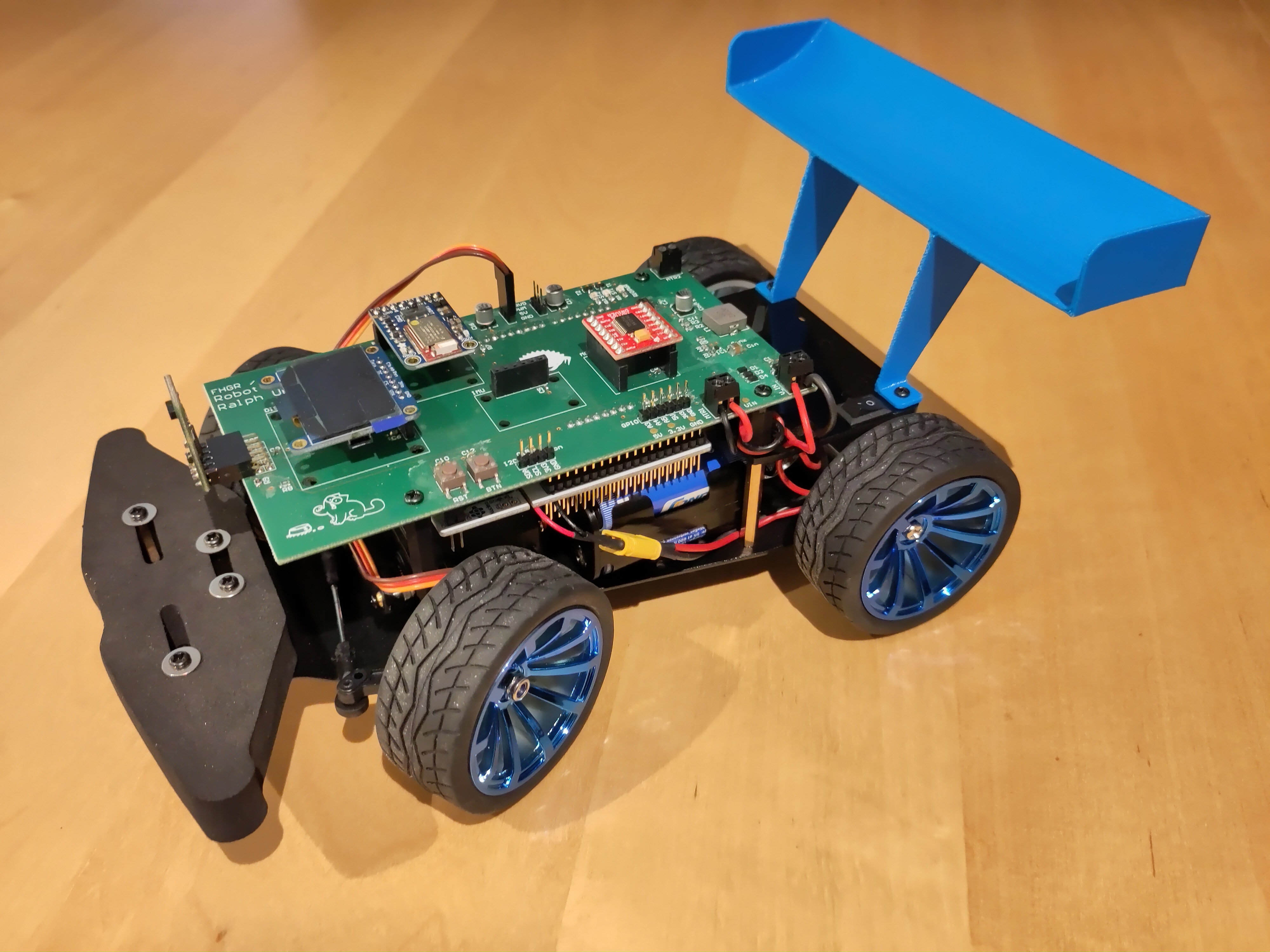
The robotcar is a small RC toy car based on the YFRobot Steering Gear Robot, using a ST Nucleo F401RE board for the microcontroller, a custom-designed PCB and a couple of add-ons (TOF sensor, bluetooth module, IMU and display).
The primary goal was to remotely control the toy car, with extended goals being that it has a simple collision avoidance by stopping if an object blocks its path and additionally a somewhat-autonomous mode where it can try to circumvent an obstacle.
User Guide
Requirements
What you'll need in order to use this robotcar:
- The robotcar
- Make sure to have charged its batteries before use!
- A smartphone, tablet or other device with a compatible app (see the from Adafruit)
- Space where you can drive the robot car around!
Prepare The Hardware
To get started follow these steps:
- Insert the batteries (beware the polarities! Supported are ca. 1.5V AA batteries) into the battery holder
- Insert the battery holder in the chassis (between the axles)
- Connect the battery holder to the car using the XD30 power connector
- Turn on the car using the switch on its rear
Connect With The App
- Open the app (e.g. Adafruit Bluefruit LE Connect on your phone)
- Connect with the app to the car
- Open the control pad (under "Controller" on the Android app)
Drive!
The following control commands are available:
- Steering left/right with the left/right arrow keys
- Increasing & decreasing the speed using the up/down arrow keys (increase/decrease speed in 25% steps, ranging from full forward to full backwards speed)
- Brake and set speed to 0 with the "1" key
The other keys are not assigned.
The car will automatically brake when you get too close to an obstacle in front. You'll still be able to reverse and steer at that moment, until the distance in front is large enough and you can drive forward again. If the car has detected an obstacle a red LED will turn on to indicate this. Once the obstacle has been cleared, the LED will turn off.
The display on the device will show the distance (in mm) to a potential obstacle in front of the car.
Hardware
The robotcar is a small RC toy car based on the YFRobot Steering Gear Robot. All electronic modules are mounted to the PCB, which in turn is mounted on the main car using stilts.
The battery module fits in nicely between the frame of the car and the Nucleo board (hanging under the PCB) and the servo and the main engine. Due to the rear stilts it has to be inserted at just the right angle, but once in it is held in place by the stilts, servo and engine. Thus, no external battery holder has been added.
A rear-mounted battery holder has been designed, but this would've had the downside of having all the weight at the rear, leading to a bad weight-balance of the car and resulting in deteriorated steering performance.
Electronics
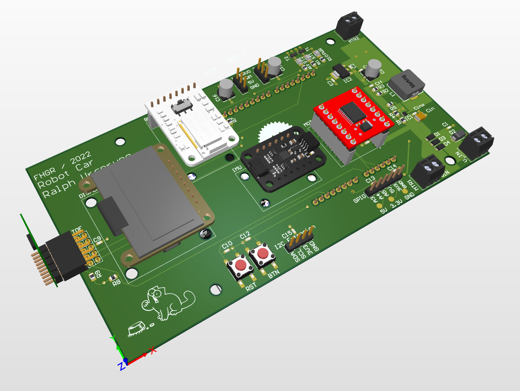
The robotcar is using a custom-designed PCB for power regulation, power distribution and general connectivity. On this, various external components are mounted.
Power is supplied by 8x AA batteries placed in a battery holder. The battery connection is done using an XD30 connector, to make it easier to remove the battery holder. A physical on/off switch is included in the power line from the XD30 connector to the PCB. This switch is not on the PCB itself because the design of the base car already included one and using that safes space on the PCB.
Schematic & PCB Design
The PCB contains the following components:
- Power regulation
- 12V DC power input
- Including EMV & polarity protection
- 12V -> 5V power regulation using a buck converter
- 5V -> 3.3V power regulation using an LDO regulator
- 12V DC power input
- Microcontroller board connector (Arduino V3 connector)
- Add-ons / 3rd party modules
- Motor Driver (SparkFun Motor Driver - Dual TB6612FNG)
- Distance Sensor (TOF, ST VL53L1X)
- Bluetooth (Adafruit Bluefruit LE UART Friend)
- IMU (Adafruit MPU6050)
- User button
- Reset button (triggers a reset of the microcontroller)
- 1 power indicator LED (shows that power is available on 5V)
- 2 status LEDs
- Connectors / debug connectors
- I2C connector
- 3 GPIO pins
- 2 connectors for servo motors
- Power measurement pads for VIN, 5V, 3.3V and GND
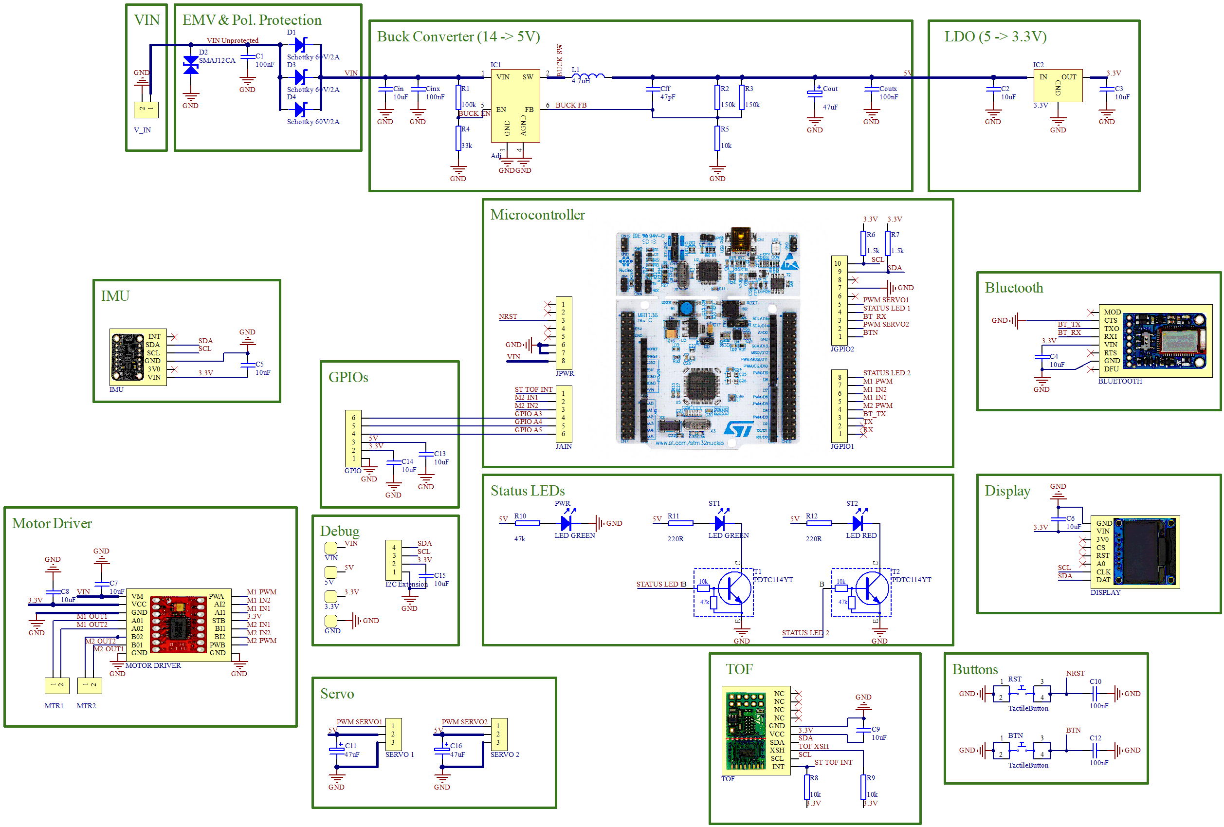
See the schematic for the details of the individual components mounted on the PCB.
Note: at the moment, the PCB schematic & layout are not published in the repository, as they rely on a FHGR-specific component library.
Power Regulation
The board is designed to be run with ca. 12V as input (8x AA batteries) and a maximum of 5A (= ca. 25W) at the input.
The board provides VIN to the motor(s) and the microcontroller board (which has its own voltage regulators), 5V to the servo(s) and 3.3V to the other components.
Each motor (only one is installed, but two would be supported) can consume up to 2A, each servo (again, only one installed but two supported) can consume up to 1A and the Nucleo board requires max. 800mA. All other components have negligible power requirements.
The layout of the buck converter and LTO has been taken from the respective datasheet (which provide best practices for the layouts).
Software
The software is implemented in Rust and uses RTIC v1 to provide RTOS-like features for interrupt/task handling.
Since Rust is not well known at FHGR (this might be the first project there using it?) some notes on it - esp. related to embedded development pertaining to this project - have been collected in an overview.
The design decisions taken for the software have been listed separately, see design decisions.
Software Architecture
As the STM32F4 is a resource-limited embedded device with a single core the application is implemented as a monolithic single-threaded application, based primarily on hardware interrupts.
Due to the way RTIC is implemented, all RTIC tasks need to be in a single rust file which contains the
rtic::app. The software has been designed in such a way that (nearly)
all hardware-specific logic is either in device-specific drivers or in this main app.
The business logic in turn is largely separate from this, with clear APIs to be called on specific hardware / timer events. This should - theoretically - allow to easily port the logic to a different microcontroller (or even a larger embedded system, e.g. a Linux-based one) without having to change the business logic.
The logic has been split so that there's a general Car representation (which doesn't know how it'll be operated) and
a separate RemoteControl (which is aware of the car and can direct it). The Car API is hardware-agnostic, i.e.
its consumers do not have to be aware of the fact that its steering is implemented using a PWM-controlled servo motor.
In the future, an AutomaticControl or similar could be added which would then implement a somewhat-autonomous mode. This
should not require changes to Car and only the RTIC code would have to be aware of it to select it and call it if data
is available (and optionally the remote control could be aware of it to allow starting/stopping the autonomous mode from there).
Interrupts
As stated, the whole behaviour is interrupt-driven. The following interrupts can trigger actions:
- TOF data available: reads the data and triggers the collision avoidance
- Bluetooth data received (either UART line idle or DMA full interrupt): handle the bluetooth message for the remote control
and act on the event (steering, speed change, etc.)
- Note: the DMA full interrupt is implemented for completeness's sake, as it could be triggered if a lot of data is sent in one go, however this is extremely unlikely as long as the standard smartphone app is being used.
- Bluetooth messages are processed with best effort, i.e. if a message (or a command within a message) is lost then no attempt is made to recover or reprocess the message. As it's based on short-term user interaction the user will most likely already have triggered the action again if it is still needed. No explicit at-most-once check is implemented because the protocol from Adafruit does not include a unique identifier for each event, but it can be presumed that under normal circumstances messages are sent only once.
- User button pressed: currently only writes a log message as the button is not used at this point
Drivers for Peripherals
The following drivers have been used for the peripherals:
| Peripheral | Driver | Comment |
|---|---|---|
| TOF Sensor (ST VL53L1X) | vl53l1x-uld | |
| Display (Adafruit 128x64 OLED Display) | ssd1306 | |
| IMU (Adafruit MPU6050) | mpu6050 | Currently unused, thus not included in the code. |
| BLE (Adafruit Bluefruit LE UART Friend) | n/a | Uses basic UART in our use-case, thus no dedicated driver needed. Protocol support implemented as part of this project in adafruit-bluefruit-protocol. Only button events are enabled here as all other events are not needed for this project. |
| Motor Driver (SparkFun Motor Driver - Dual TB6612FNG) | tb6612fng | Implemented as part of this project. |
Details
The code should be largely self-explaining, but comments have been added. The generated documentation is also published here.
You can also generate it for yourself by running cargo doc --open in the repository root.
Compiling & Running It
Please refer to the README located in the repository root for the necessary steps to compile & run the program on the target device.
Rust (Embedded) Specifics
For a general overview of Rust please refer to the awesome Rust learning resources, and for more details on embedded development with Rust please refer to the awesome Rust Embedded learning resources. The same also goes for further information on RTIC.
There's also a community blog post which contains similar information to what's been listed here.
This page is not meant to teach you how to program in Rust, and it's not meant as original research. Instead, this is a very quick overview of the things which might be relevant in this project. Please do read through the learning resources linked above to get a proper understanding of these concepts.
Crates
Rust libraries are called crates and are often published on crates.io (but can also be pulled in from other sources, e.g. local paths or git repositories).
Cargo is the package manager and build tool of Rust which also handles the crates being used.
Variable Ownership & Lifetimes
Rust has a strong concept of ownership of data. References to data in turn is tracked with lifetimes for the reference. The combination of these two concepts lets the compiler do strict validation of data flow to prevent many of the known implementation errors which lead to hard-to-track problems (use-after-free, multiple threads accessing the same variable without locking, etc.).
This sometimes leads to different implementations as one might be used to from casual C/C++ code which is less strict in this regard.
Embedded-Specific
no_std: No Standard Library
"Normal" Rust programs are compiled against with backing support of a standard library backed by an OS. This standard library provides a variety of useful features. Since we are running on bare metal, we cannot make use of this and thus lose access to these nice features.
However, also in no_std certain features are still available: anything which isn't OS-specific and doesn't need a
memory allocator to work (i.e. the size is known at compile-time) is available in core
which is always present.
Optionally, an allocator can be added (if available / implemented for the used target) and in that case alloc
can be used as well. This will provide all OS-independent but dynamically allocated APIs (e.g. string handling).
Different Hardware Abstractions
By convention there are different "levels" of abstraction when interacting with hardware in Rust. From the bottom up (higher is preferred):
- No abstraction, know the memory location of registers and directly manipulate them (requires
unsafeRust, bound to specific hardware) - Peripheral Access Crate (PAC): low-level APIs to interact with the registers of a specific device.
Usually generated from SVD files using
svd2rust. Still requires someunsafecode and offers nearly no hardware abstraction, i.e. you still need to interact with the registers, but don't need to know the memory addresses. - Hardware Abstraction Layer (HAL): higher-level APIs to interact with a specific device (or often device family).
Usually no
unsafeRust is needed. Offers APIs like "set this output port to high". - Board Support Package (BSP): high-level APIs for specific boards, offering opinionated APIs for that board (e.g. directly turning specific pins into inputs or outputs because they are known to be connected to certain peripheral mounted on the board and offering them under the appropriate name).
See the embedded Rust book for more details.
Besides this, there are also drivers for peripherals, which are generally agnostic to the specific environment where
they're being run on, thanks due to abstraction layers like embedded-hal.
Generic HAL: embedded-hal
The Rust embedded community offers a generic set of APIs for HALs: embedded-hal.
Similar abstractions exist for other embedded features (embedded-nal
for networking, embedded-can for CAN, etc.).
(Nearly?) all HALs implement these APIs when appropriate. This allows writing device-independent functionality,
e.g. drivers for peripherals, which can then run on any device.
Thus, often only the initialisation code has to be device-specific, while the business logic can use the traits and is thus portable.
Knurling-rs: Rust Embedded Improvement Project
Knurling-rs is a project by the Rust community (mainly driven by Ferrous Systems) to improve the tooling for embedded development in Rust. This has resulted in various tools which are also being used in this project here:
Logging: defmt
Logging is implemented using defmt. This is a deferred formatting logging framework:
the source code includes the whole log message, but at compile time this is split up:
- logging calls below the selected log level are removed
- the format strings are compiled into a table of string literals which is not part of the final program loaded on the device
- the device only knows the index of the format string and sends that plus the arguments to the listener
This way, the binary size is (drastically) reduced compared to having all the string handling in the binary.
defmt is widely supported in the Rust Embedded ecosystem, most crates
Device Connection: probe-run
probe-run supports downloading the application to the microcontroller, abstracting
away from the specific microcontroller and connection type (JLink, etc.). It also supports showing the log messages of
defmt when running an application.
It can easily be integrated with Cargo to support directly running the application with the standard cargo run command
(and the corresponding integration in IDEs).
Design Decisions
The following sub-pages will list the reasons for various design decisions in the software.
Programming Language
The course suggestion is to program in C (or C++) and use STM32CubeIDE to generate the microcontroller-configuration (setting pins as input/output, setting up I2C, etc.), but this was not a hard requirement.
I chose Rust for the following reasons:
- It is a systems programming language with similar performance to C/C++
- The language offers many memory-safety related features which C & C++ lack
- There are many companies and projects which have done research on this and come to the conclusion that this can't be solved
with C/C++ and are moving towards Rust, e.g.:
- Linux Kernel 6.1 with Rust Support for Drivers
- Android: Memory Safe Languages in Android 13
- Microsoft Security Response Center: Blog Series on Memory Safety
- Microsoft Azure CTO Statement
- AWS loves Rust
- Mozilla is oxidating Firefox
- Chromium supports Rust
- Tangram Vision: Why Rust for Robots?
- tonari: 3K, 60fps, 130ms: achieving it with Rust
- There are many companies and projects which have done research on this and come to the conclusion that this can't be solved
with C/C++ and are moving towards Rust, e.g.:
- Embedded development is nowadays well-supported in Rust:
- Active community around it (incl. a working group)
thumbv7em-none-eabihf(for our STM32F4 chip) is a tier 2 target for the compiler- HAL implementations available for all relevant chips
- Drivers (target-agnostic, based on
embedded-haltraits) exist for a lot of peripherals - Frameworks for many common functionalities exist
- Various RTOS and RTOS-like frameworks exist
- Due to the
embedded-halabstraction most of the code can be written in a device-agnostic manner, making it more portable. - The language offers many more modern, concise ways of writing code compared to C/C++
- Personal reasons
- While I had used Rust before, I had never used it for embedded development and wanted to explore this use-case
- I wanted to show Rust as an alternative to C/C++ for the FHGR
Base Frameworks
There were several options of frameworks available to implement this project.
Overview of the Possibilities Analysed
No Framework
It is of course possible to just use the HAL and implement the functionality directly like this. However, when working with interrupts, this complicates things as one has to manually take care of avoiding race conditions and managing resource sharing.
RTIC
RTIC is a concurrency framework to take care of resource sharing and task priorities when working with interrupts (hardware
and software tasks are supported). RTIC v1 does not support async Rust code.
Embassy
Embassy brings async support to embedded Rust by providing an executor. It also brings its own HAL to offer a more
streamlined abstraction over different devices and to have an async-enabled HAL (the HAL can theoretically be used without
the executor and vice versa).
At the moment (January 2023) Embassy does not yet have released crates (git dependencies have to be used instead, a v0.1 release is being worked to) and requires a nightly rust compiler (due to the usage of some language features which have not yet been stabilised).
Decision
Due to the need for the use of interrupts not using a framework was not an option (seeing that frameworks are available). While Embassy looks very promising, the lack of a stable release and the requirement for nightly Rust it however felt premature to use it for this project. This led to the decision for RTIC.
Note that no board support package has been used for the Nucleo F401RE because none of the board-specific features is being used (and also, the available nucleo-f401re crate wouldn't offer too much in terms of additional features besides access to the LED and button (neither of which is accessible with the board mounted underneath the PCB)).
TOF Sensor
The standard TOF sensor provided for the project was the ST VL53L3CX (specifically it was provided in the format of the ST VL53L3CX-SATEL breakout board). There was no existing Rust driver available for this when starting the project. Rewriting the driver in Rust was not feasible in the timeframe as the original C driver from ST contains thousands and thousands of lines of code with a lot of logic (most of the logic for this sensor is not running on the sensor chip but is instead in the driver).
Design Of C-based ST TOF Drivers
The C implementation of drivers for the TOF sensors provided by ST follow a common pattern:
- Platform-independent logic is implemented by them
- You have a platform-specific implementation which instantiates the driver and has a
struct(which is then passed to the driver) which can afterwards be used to handle communication - They provide a platform-specific header file with APIs which they call, and you have to implement it (e.g. I2C communication;
the aforementioned custom, platform-specific
structis used for this)
Using FFI (Foreign Function Include) To Use The C Driver
My first approach was to use FFI to be able to use the ST-provided driver and call the C code from Rust (to interact with it) and call Rust from C (to handle the I2C communication).
While I was able to get the Rust to C and C to Rust calls working, the driver wouldn't start up completely due to wrong
data being read from the sensor. Debugging the I2C calls showed that most of them returned the exact same values as when
using the Arduino C++ code (it was faster to get that one running & debugged than the C-based driver, but their logic is
the same, and they're both from ST themselves). However, certain reads (always the same ones in each run) would just return
0x00 instead of the expected value.
Using An Alternative TOF Sensor
ST manufactures multiple different TOF sensors and offers them on the same breakout board format (i.e. they are pin compatible). Namely, the ST VL53L1X (with the ST VL53L1X-SATEL breakout board) offers a similar ranging distance (most others were too short for our use-case) and already has a Rust driver (which is even fully implemented in Rust - this sensor runs more logic on-chip and thus has a smaller driver).
Decision
Due to the amount of time already invested in trying to get the VL53L3CX driver running and the cheap cost of just getting another TOF I went for the VL53L1X and used the existing driver, which worked well.
Stack Overflow Protection
flip-link flips the memory layout of embedded programs to protect against stack overflows.
It has been added to this project because it's best practices to have it enabled, as it helps track down stack overflows.
See the flip-link documentation for a more detailed explanation of how it works (incl. nice graphics!).
Future Steps
This page lists things which should or could still be implemented for this robot car. For a complete list of all open points see the issues on GitHub.
Fix Intermittent Hangs (#29)
It currently happens that the application crashes and is stuck. It is unclear why this happens (lack of time to debug it) and needs further investigation. Usually, power-cycling helps (which also fully resets the peripherals, compared to just resetting the microcontroller).
So far it seems to be related to I2C communication with the TOF.
Use IMU For Braking Distance (#27)
Currently, the automatic braking collision avoidance uses a fixed distance at which it will engage. Instead of this, the IMU could be used to acquire the current velocity (by integrating over the acceleration) which in turn could be used to calculate the minimum safe distance needed to come to a full stop.
Implement Simple Autonomous Mode (#11)
An alternative to just braking as a collision avoidance would be to try and circumnavigate the obstacle (presuming that this is possible for the obstacle). As the TOF sensor is mounted in a fixed forward-facing position this would probably need some jiggling motion of the car to occasionally turn slightly and check if the obstacle is still on its side.
A physical user button and two LEDs are available on the PCB and currently unused. These could be used to start the autonomous mode and indicate the current status (besides showing information on the display).
Use a Memory Allocator (#30)
Currently, the software does not use a memory allocator. It would be possible to add embedded-alloc
which would then e.g. allow using string formatting at runtime for the messages on the display.
Also, the adafruit-bluefruit-protocol could then use the
alloc::Vec instead of the non-alloc Vec from heapless.